Access the Steel Code Check spreadsheet
by selecting the Results menu and then selecting Members![]() Steel Code Checks.
Steel Code Checks.

Note:
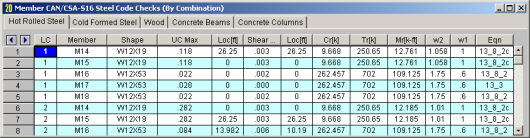
The UC Max value represents the maximum Unity Check value produced by the interaction of the axial and bending stresses. This would be a factored ratio of actual to allowable stress, or demand vs capacity. The governing code equation that resulted in this value is displayed in the far right column for reference as well.
The Shear UC represents a similar ratio based on the shear provisions of the design code. The location for the shear check is followed by "y" or "z" to indicate the direction of the shear.
Generally, if UC Checks are less than 1.0, the member is considered passing. If either of them is greater than 1.0, the member is considered failing. If the value is greater than 9.999 it will be listed as "9.999".
The remaining columns, discussed below, provide some of the values used in the code check with the equation number itself given in the last column. The Member Detail Report gives more values used to perform the code check.
The Loc field tells at what location the maximum code check occurs measured from the I-joint location (starting end) of the member. See Model Display Options – Members to learn how to view the code check results graphically.
The moving load results are enveloped and the governing load combination and step location is shown for each result value under the "LC" column. The first number is the load combination, the second is the step number: (load combination - step number). See Moving Loads to learn more.
For ASD 13th, 14th, and 15th Edition code checking, Pnc/Om, Pnt/Om, Mnyy/Om and Mnzz/Om are the design capacities divided by the Omega safety factors. Whereas the LRFD code checks will display the capacities multiplied by the Phi factor: Phi*Pnc, Phi*Pnt, Phi*Mnyy, and Phi*Mnzz.
For Pnc is calculated according to the provisions of Chapter E in the AISC 13th, 14th, or 15th Editions. Pnt is based on Chapter D. The Mn values are calculated based on Chapter F. Note that for RISA-2D, "zz" corresponds to "xx" in the AISC code, i.e. RISA-2D substitutes Mnzz for Mnx, to maintain consistency with the member local axis system.
Note:
The Cb coefficient is calculated based on the description presented in Chapter F, section F1. Refer to the section on Cb input for more information about this calculation.
Tapered Wide Flanges (ASD) - For Tapered WF shapes, the Cb value shown will be the Cb value that RISA-2D calculated internally, NOT the value that was entered and used for the “B” value. The values shown in the Cm fields will be the C'm values that were used for the Appendix F calculations. The controlling equation from Appendix F will be listed.
Tapered Wide Flanges (LRFD) - For Tapered WF shapes, the Cb value shown will be the Cb value that RISA-2D calculated, NOT the Cb value that was entered and used for the “B” value. The controlling equation from Chapter H will be listed.
The final field lists the controlling equation for the code check. This will be one of the equations from Chapter H (for ASD and LRFD) or section 7 for the HSS code. If there is no moment demand in the member being checked, then the program will calculate the unity ratio using Chapter D where it compares the axial demand to the axial capacity of the member using Pu/(Phi*Pc).
Note:
For enveloped results the combination that produced the listed code and shear checks is given in the"LC" column. The other values are the corresponding values and are not necessarily the maximums across all the combinations.
Access the Steel Code Check spreadsheet
by selecting the Results menu and then selecting Members![]() Steel Code Checks.
Steel Code Checks.
Note:
The UC Max value represents the maximum Unity Check value produced by the interaction of the axial and bending stresses. This would be a factored ratio of actual to allowable stress, or demand vs capacity. The governing code equation that resulted in this value is displayed in the far right column for reference as well.
The Shear UC represents a similar ratio based on the shear provisions of the design code. The location for the shear check is followed by "y" or "z" to indicate the direction of the shear.
Generally, if UC Checks are less than 1.0, the member is considered passing. If either of them is greater than 1.0, the member is considered failing. If the value is greater than 9.999 it will be listed as "9.999".
The remaining columns, discussed below, provide some of the values used in the code check with the equation number itself given in the last column. The Member Detail Report gives more values used to perform the code check.
The Loc field tells at what location the maximum code check occurs measured from the I-joint location (starting end) of the member. See Model Display Options – Members to learn how to view the code check results graphically.
Cr, Mryy and Mrzz are the factored resistances calculated for the member. Cr is the compressive resistance, calculated according to the provisions of the design code. The Mr values are the moment resistances, calculated based on provisions of the design code. Note that for RISA-2D, "zz" corresponds to "xx" in the Canadian code, i.e. RISA-2D substitutes Mrzz for Mrx, to maintain consistency with the member local axis system.
Note:
The w2 coefficient is calculated based on the description presented in Section 13.6. Whether or not the member is subject to sidesway is determined from the setting for the strong axis sway flag on the Member Design spreadsheet. The w1 coefficients, described in Section 13.8.4 are also listed. These are also influenced by the sway flag settings.
Tapered Wide Flanges - For Tapered WF shapes, the provisions of the AISC LRFD 2nd code are used. The w2 value shown will be the w2\Cb value that RISA-2D calculated, NOT the w2 value that was entered and used for the “B” value. The controlling equation from Appendix F in the LRFD code will be listed. The values shown under the headers for Cr and Mr will instead be the Pn and Mn values calculated for the LRFD code. These are the unfactored member strengths. (Similar to Cr and Mr, but without the “phi” reduction factor.)
The final field lists the controlling equation for the code check. This will be one of the equations from Section 13.8.1, 13.8.2, or 13.9.
Note:
For enveloped results the combination that produced the listed code and shear checks is given in the"LC" column. The other values are the corresponding values and are not necessarily the maximums across all the combinations.
Access the Steel Code Check spreadsheet
by selecting the Results menu and then selecting Members![]() Steel Code Checks.
Steel Code Checks.
Note:
The UC Max value represents the maximum Unity Check value produced by the interaction of the axial and bending stresses. This would be a factored ratio of actual to allowable stress, or demand vs capacity. The governing code equation that resulted in this value is displayed in the far right column for reference as well.
The Shear UC represents a similar ratio based on the shear provisions of the design code. The location for the shear check is followed by "y" or "z" to indicate the direction of the shear.
Generally, if UC Checks are less than 1.0, the member is considered passing. If either of them is greater than 1.0, the member is considered failing. If the value is greater than 9.999 it will be listed as "9.999".
The remaining columns, discussed below, provide some of the values used in the code check with the equation number itself given in the last column. The Member Detail Report gives more values used to perform the code check.
The Loc field tells at what location the maximum code check occurs measured from the I-joint location (starting end) of the member. See Model Display Options – Members to learn how to view the code check results graphically.
The shear capacity, Pv, is calculated per section 4.2.3 using the listed equations for the shear area of each section type. Shear buckling per section 4.4.5 is also considered.
The reduction in design strength, “py”, per table 9 in section 3.1.1 is automatically considered by the program. The reduction is based on the yield stress of the steel material used for the member and the maximum thickness of the cross section.
The compression capacity, Pc is calculated based on section 4.7. The effective lengths shown in table 22 are shown as “K” factors in the program ( K*length is the effective length) and these can be approximated by the program based on the sway flags and the end release conditions of the member (the connection type is NOT considered.) The user can also specify the effective length by entering the appropriate K factor.
For the case of a sway member having pinned ends, a value of 2.1 for K is used as table 22 does not address this condition. The program considers all H sections as I sections for purposes of picking the proper strut curve in table 23 in section 4.7.5. For the same table and section, the program does not do interpolation for shapes that have maximum thicknesses between 40 and 50 mm, per footnote 1.
The tension capacity, Pt, is calculated based on section 4.6 and currently done using the gross section.
Width to thickness checks are done for all shapes based on Tables 11 and 12 in section 3.5. Complete Effective section properties for the Area, Plastic Modulus, and Section Modulus, are done per section 3.5.6 and 3.6.
The moment capacity, Mc, is calculated per section 4.2.5, including consideration for the amount of shear at the section. The limit states of lateral torsional buckling, per section 4.3.6 and web buckling per section 4.4.4.2 are also considered.
The equivalent uniform moment factors (my, mz, mLT) used in section 4.8.3 and shown in table 26 of section 4 are calculated automatically by the program based on the sway flag and member moment diagram. The user can also enter their own values.
The final field lists the controlling equation for the code check. Combined axial and bending stresses are computed based on the equation shown in section 4.8, with the governing equation reported. Combined bending and warping is calculated per the AISC specification and design guide.
Biaxial bending and biaxial shears on Pipes and solid circular bars are done using the square root sum of the squares of the forces applied in or about the local y and local z directions.
For enveloped results the combination that produced the listed code and shear checks is given in the"LC" column. The other values are the corresponding values and are not necessarily the maximums across all the combinations.
Access
the Steel Code Check spreadsheet by selecting the Results
menu and then selecting Members ![]() Steel Code
Checks.
Steel Code
Checks.
Note:
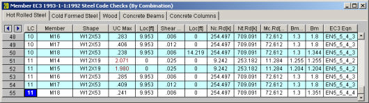
The UC Max value represents the maximum Unity Check value produced by the interaction of the axial and bending stresses. This would be a factored ratio of actual to allowable stress, or demand vs capacity. The governing code equation that resulted in this value is displayed in the far right column for reference as well.
The Shear UC represents a similar ratio based on the shear provisions of the design code. The location for the shear check is followed by "y" or "z" to indicate the direction of the shear.
Generally, if UC Checks are less than 1.0, the member is considered passing. If either of them is greater than 1.0, the member is considered failing. If the value is greater than 9.999 it will be listed as "9.999".
The remaining columns, discussed below, provide some of the values used in the code check with the equation number itself given in the last column. The Member Detail Report gives more values used to perform the code check.
Important Notes:
The Loc field tells at what location the maximum code check occurs measured from the I-joint location (starting end) of the member. See Model Display Options – Members to learn how to view the code check results graphically.
The compression capacity, Nc.Rd is calculated based on section 62.4 and 6.3.1. The effective lengths shown in tables E.2.1 and E.2.2 of the 1992 Eurocode are shown as “K” factors in the program ( K*length is the effective length.) These can be approximated by the program based on the sway flags and the end release conditions of the member (the connection type is NOT considered.) The approximate K factor values for reasonable “pinned” and “fixed” conditions are taken from the British BS 5950-1:2000 code. The user can also specify the effective length by entering the appropriate K factor. For the case of a sway member having pinned ends, a value of 2.1 for K is used as a reasonable limit.
The tension capacity, Nt.Rd, is calculated based on section 6.2.3 and currently done using the gross section.
Width to thickness checks are done for all shapes based on table 5.2 from the 2005 EuroCode.
The shear capacity, Vpl.Rd, is calculated per section 6.2.6 using the listed equations for the shear area of each section type. Shear buckling per section 5.6.3 of the 1992 Eurocode is also considered.
The moment capacity, Mc.Rd, is calculated per section 6.2.5, including consideration for the lateral-torsional buckling.
The equivalent uniform moment factors (Cm & CmLT per the 2005 code) are calculated per Table B.3 of Annex B unless they are manually input by the user in the Member Design Properties spreadsheet.
The equivalent uniform moment factors (βm & βmLT per the 1992 code) used in section 5.5.4 and shown in figure 5.5.3 of section 5.5.4 are calculated automatically by the program based on the sway flag and member moment diagram unless they are manually input by the user in the Member Design Properties spreadsheet.
The final field lists the controlling equation for the code check. Combined axial and moment is checked for the limit state of stress and high shear, The limit states of flexural buckling and lateral torsional buckling as well as web buckling are also considered. The governing section is also reported. Combined bending and warping is calculated per the AISC specification and increases the moment about the y-y axis.
Biaxial bending and biaxial shears on Pipes and solid circular bars are done using the square root sum of the squares of the forces applied in or about the local axes.
For enveloped results the combination that produced the listed code and shear checks is given in the"LC" column. The other values are the corresponding values and are not necessarily the maximums across all the combinations.
Access
the Steel Code Check spreadsheet by selecting the Results
menu and then selecting Members ![]() Steel Code
Checks.
Steel Code
Checks.
Note:
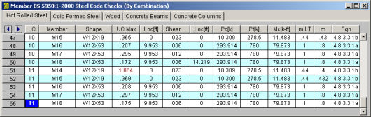
The UC Max value represents the maximum Unity Check value produced by the interaction of the axial and bending stresses. This would be a factored ratio of actual to allowable stress, or demand vs capacity. The governing code equation that resulted in this value is displayed in the far right column for reference as well.
The Shear UC represents a similar ratio based on the shear provisions of the design code. The location for the shear check is followed by "y" or "z" to indicate the direction of the shear.
Generally, if UC Checks are less than 1.0, the member is considered passing. If either of them is greater than 1.0, the member is considered failing. If the value is greater than 9.999 it will be listed as "9.999".
The remaining columns, discussed below, provide some of the values used in the code check with the equation number itself given in the last column. The Member Detail Report gives more values used to perform the code check.
The Loc field tells at what location the maximum code check occurs measured from the I-joint location (starting end) of the member. See Model Display Options – Members to learn how to view the code check results graphically.
The allowable compressive stress, Fa, is calculated based on section 5.1. The effective lengths shown in table 5.2 are shown as “K” factors in the program ( K*length is the effective length) and these can be approximated by the program based on the sway flags and the end release conditions of the member (the connection type is NOT considered.) The user can also specify the effective length by entering the appropriate K factor. For the case of a sway member having pinned ends, a value of 2.1 for K is used as table 5.2 does not address this condition.
The allowable tensile stress, Ft, is calculated based on section 4.1 and is currently done using the gross section.
The maximum slenderness ratios shown in table 3.1 are reported in the warning log when they are exceeded. The program still calculates capacities for the members and reports a code check.
Width to thickness checks are done for all shapes based on section 3.5.2.1. Complete effective section properties for the Area and Section Modulus are calculated.
The allowable shear stress, Fv, is used per section 6.4.1. This value is checked per the maximum shear stress in the section based on elastic theory.
The strong axis allowable bending stress, Fb, is calculated per section 6.2. The limit state of lateral torsional buckling, per sections 6.2.4 and 6.2.6, is considered. The allowable bending stress is increased per section 6.2.4.1 as appropriate. The weak axis bending stress is assigned per section 6.2.5.
The equivalent uniform moment factor, Cm, used in section 7.1 are calculated automatically by the program based on the sway flag per section 7.1.3. The user can also enter their own values in the Member Design Parameters spreadsheet.
The final field lists the controlling equation for the code check. Combined axial and bending stresses are computed based on the equations shown in section 7.1,with the governing equation reported. Combined bending and warping is calculated per the AISC ASD specification.
Biaxial bending and biaxial shears on Pipes and solid circular bars are done using the square root sum of the squares of the forces applied in or about the local y and local z directions.
For enveloped results the combination that produced the listed code and shear checks is given in the"LC" column. The other values are the corresponding values and are not necessarily the maximums across all the combinations.
Access
the Steel Code Check spreadsheet by selecting the Results
menu and then selecting Members ![]() Steel Code
Checks.
Steel Code
Checks.
Note:
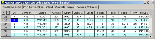
The UC Max value represents the maximum Unity Check value produced by the interaction of the axial and bending stresses. This would be a factored ratio of actual to allowable stress, or demand vs capacity. The governing code equation that resulted in this value is displayed in the far right column for reference as well.
The Shear UC represents a similar ratio based on the shear provisions of the design code. The location for the shear check is followed by "y" or "z" to indicate the direction of the shear.
Generally, if UC Checks are less than 1.0, the member is considered passing. If either of them is greater than 1.0, the member is considered failing. If the value is greater than 9.999 it will be listed as "9.999".
The remaining columns, discussed below, provide some of the values used in the code check with the equation number itself given in the last column. The Member Detail Report gives more values used to perform the code check.
The Loc field tells at what location the maximum code check occurs measured from the I-joint location (starting end) of the member. See Model Display Options – Members to learn how to view the code check results graphically.
The allowable compressive stress, Phi*N, is calculated based on clause 6.3. The effective lengths shown in Figure 4.6.3.2 are shown as “K” factors in the program ( K*length is the effective length) and these can be approximated by the program based on the sway flags and the end release conditions of the member (the connection type is NOT considered.) The user can also specify the effective length by entering the appropriate K factor.
The allowable tensile stress, Phi*Nt, is calculated based on clause 7.2 and is currently done using the gross section.
Width to thickness checks are done for all shapes based on Table 5.2. Complete effective section properties for the Area and Section Modulus are calculated.
The allowable shear stress, Phi*Vv, is used per clause 5.11. This value is checked per the maximum shear stress in the section based on elastic theory.
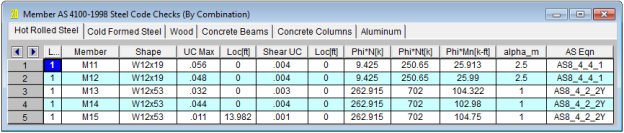
The strong axis allowable bending stress, Phi*Mn, is calculated per section 5. The limit state of lateral torsional buckling, per clause 5.6 is considered.
The moment modification factor, Alpha_m, is calculated automatically by the program based on clause 5.6.1.1. When explicit unbraced lengths are used, the program does not have the member segment information to calculate alpha_m. It will conservatively assume alpha_m to be 1.0. The user can also enter their own values in the Member Design Parameters spreadsheet.
The final field lists the controlling equation for the code check. Combined axial and bending stresses are computed based on the equations shown in clause 8.4, with the governing equation reported. Combined bending and warping is calculated per the AISC ASD specification.
Biaxial bending and biaxial shears on Pipes and solid circular bars are done using the square root sum of the squares of the forces applied in or about the local y and local z directions.
For enveloped results the combination that produced the listed code and shear checks is given in the"LC" column. The other values are the corresponding values and are not necessarily the maximums across all the combinations.
Access
the Steel Code Check spreadsheet by selecting the Results
menu and then selecting Members![]() Steel Code
Checks.
Steel Code
Checks.
Note:
The UC Max value represents the maximum Unity Check value produced by the interaction of the axial and bending stresses. This would be a factored ratio of actual to allowable stress, or demand vs capacity. The governing code equation that resulted in this value is displayed in the far right column for reference as well.
The Shear UC represents a similar ratio based on the shear provisions of the design code. The location for the shear check is followed by "y" or "z" to indicate the direction of the shear.
Generally, if UC Checks are less than 1.0, the member is considered passing. If either of them is greater than 1.0, the member is considered failing. If the value is greater than 9.999 it will be listed as "9.999".
The remaining columns, discussed below, provide some of the values used in the code check with the equation number itself given in the last column. The Member Detail Report gives more values used to perform the code check.
The Loc field tells at what location the maximum code check occurs measured from the I-joint location (starting end) of the member. See Model Display Options – Members to learn how to view the code check results graphically.
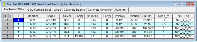
The allowable compressive stress, Phi*N, is calculated based on clause 6.3. The effective lengths shown in Figure 4.6.3.2 are shown as “K” factors in the program ( K*length is the effective length) and these can be approximated by the program based on the sway flags and the end release conditions of the member (the connection type is NOT considered.) The user can also specify the effective length by entering the appropriate K factor.
The allowable tensile stress, Phi*Nt, is calculated based on clause 7.2 and is currently done using the gross section.
Width to thickness checks are done for all shapes based on Table 5.2. Complete effective section properties for the Area and Section Modulus are calculated.
The allowable shear stress, Phi*Vv, is used per clause 5.11. This value is checked per the maximum shear stress in the section based on elastic theory.
The strong axis allowable bending stress, Phi*Mn, is calculated per section 5. The limit state of lateral torsional buckling, per clause 5.6 is considered.
The moment modification factor, Alpha_m, is calculated automatically by the program based on clause 5.6.1.1. The user can also enter their own values in the Member Design Parameters spreadsheet.
The final field lists the controlling equation for the code check. Combined axial and bending stresses are computed based on the equations shown in clause 8.4, with the governing equation reported. Combined bending and warping is calculated per the AISC ASD specification.
Biaxial bending and biaxial shears on Pipes and solid circular bars are done using the square root sum of the squares of the forces applied in or about the local y and local z directions.
For enveloped results the combination that produced the listed code and shear checks is given in the"LC" column. The other values are the corresponding values and are not necessarily the maximums across all the combinations.
The spreadsheet results for tapered members gives the same information as other AISC Code Checks. However, the Detail Reports for tapered members designed to AISC Design Guide 25 give some additional information.
As shown in the image below, the code checks list the member capacity calculated for axial, flexure, and shear. In addition to the capacity values, the table reports the equation number used to arrive at that capacity and the failure mode which caused it (please see the example below). The table also gives the slenderness parameters that apply for that failure state.
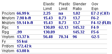
The following failure modes are listed for axial and strong axis bending:
Please see the Tapered Member design topic for more information about these limit states.